Tuesday 31 December 2013

Custom steering boss

For the IVA test in June I did not fit the aero screen as the general advice was not to provoke the testing sharp edges rules. I therefore fitted a cheap steering wheel with lots of padding that would give me a good view of the instruments and satisfy the IVA man.

After the IVA test I immediately fitted the aero screen, wanting to take it touring in Scotland and not having to wear a helmet all the time. That is when the trouble started. The 300mm steering wheel now fouled the aero screen. To save having the car off the road in prime blatting season I elected to fit a small 250mm D shaped sports wheel. The clearance and driving position was now fine but the very positive steering and view of the instruments was poor. At that time I decided to put the problem off for another day.

Aero screen with sports wheel

Over the Christmas 2013 break I decided not to put it off any longer. I ordered up a 120mm diameter round billet bar 2" deep from the local metal merchants. This is pretty well the limit of what I can easily turn in my small lathe. To make it easier to mount in the chuck, first off I put a 2" hole down the centre using a Rota-broach hole cutter. (*) see note

The final boss had 18 radial holes:
* 6 to mount the steering wheel flange
* 6 recessed holes to mate with the existing collapsible boss
* 6 to mount the cover plate
However you need a rotary table or indexer to accurately position these holes or an incredible amount of luck.

The resulting wheel is much improved classic style suiting the car and owner.


See clearance S/W to plexiglass

Dashboard side

Profile with additional 20mm clearance
Contents

http://sylvabuild.blogspot.co.uk/2012/01/sylva-j15-is-kit-car-designed-by-jeremy.html

Note(*):For those who have not discovered Rota-broaches you don't know what you are missing. They are precision hole saw (you do need a vertical drill to use them however).

Thursday 19 December 2013

Tonneau design

This page is intended to illustrate the wonderful work that Karen did who made my Tonneau. The original pattern was made of Toolstation groundsheet and marked up with paint stick then cut out with sissors. This is not Karen's main job but I think you will agree she has made a fine job. The first test will be on the road to Applecross soon with the Westfield Club (WSCC).

View from front

Rear off side


Contents

http://sylvabuild.blogspot.co.uk/2012/01/sylva-j15-is-kit-car-designed-by-jeremy.html

Monday 16 December 2013

Fuel System modifications

I have had to make a number of modifications to the original fuel system design as a result of experience when using the car. The first sign of trouble was on my return from the IVA, I decided to top up the tank in my garage and to my horror the tank was pressurised, the cap just about blew my head off.

The second problem is the fuel gauge, despite my efforts to make it accurate, was not. It was telling me it was empty and it had 1.5Gallons left. The standard VDO gauge is 380mm and the tanks as designed is 420mm. 40mm is roughly equivalent to the error of the gauge.

I had a read at the forums particularly on the matter of pressurisation and it turns out that HP fuel systems can cause this problem particularly when there is no room for expansion in the tank and where a simple one way valve is fitted. The fuel comes back from  the fuel rail slightly temperature elevated and therefore wants to expand the fuel in the tank. The one way valve compounds the problem as it is designed to let air in and not out. There is also a charging of the tank when you start the car up for the first time. Repeated start stop compounds the problem.

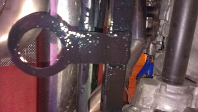
There is a valve called a Mocal valve that is designed to alleviate these problems as it works in both directions with limitations of course. This valve has a 0.5 bar negative inlet trigger point and a 0.75 bar positive pressure relief threshold. This is an expensive part ~£60 from various sources.

I fitted the Mocal valve and although this prevented the tank pressurising it dumped neat fuel occasionally under the car. My driveway has a 15deg slope and when driving up, the two way valve becomes temporarily blocked by fuel and then when the tank becomes pressurised it dumps neat fuel into the overflow till equilibrium is reached within the tank at 0.75 bar.

This in my opinion is an inherent problem with aero style tanks where the Mocal valve has to be connected at the same height a the top of the tank. It would be slightly easier if there was a filler neck, where no fuel was present and no fuel would be expelled.

The puma ECU has provision for a Carbon filter for such an eventuality along with a solenoid valve. When you are above a certain rev range it dumps the filtered fuel into the inlet manifold and weakens the mixture from the fuel rail. All by computer control.

I decided not to use that system as I had nowhere to put a carbon filter and I had no idea what would have happened with my variation in the design of the fuel system.

I pondered the issue for several weeks and came up with a three part solution.

* I install a fuel filler pot with a one way lead free valve from Car Builders Solution. The design of which forced a 45mm air gap at the top of the tank. No matter how hard you try it will not allow filling of the tank beyond a -45mm limit.
* Installed an overflow container with a glass bowl so I can keep an eye on any overflow events from the Mocal valve. It turns out it only overflows after driving up the driveway, after the tank has been filled and then only a very small quantity of fuel is discharged. The overflow reservoir can be emptied occasionally. Better than leaking fuel at the pits or the start line.
* Modified the VDO sender to read correctly by extending the range. I don't have any pictures of this modification, trust me it was difficult.

The overflow reservoir was made out of a large fuel filter from a large us car or lorry obtained from ebay.


Modified fuel system

Overfill protector
Mocal valve and overflow reservoir
Contents

http://sylvabuild.blogspot.co.uk/2012/01/sylva-j15-is-kit-car-designed-by-jeremy.html


Sunday 15 December 2013

Towing points

I have not taken the Sylva around a race track however I have taken it around the MSCC Forestburn hill climb track. One of the features missing is front and rear tow points. If nothing else it is fairly essential for getting the car on the trailer on your own.

The rear presented little challenge, I made a steel loop out of 4mm sheet with the plasma cutter. And cut a hole with a Rotabroach (Mag Drill / annular cutter) the appropriate size, enough to leave sufficient strength in the loop.

The front presented a bigger challenge. I needed something that attached to the chassis but avoided fouling the front bonnet/hood while accessing while opening and closing it (refuelling etc).

For the front I obtained a MSA compliant adjustable towing loop that extends beyond the GRP bonnet/hood and clips on to it with a press stud. The adjustable nature of the front tow loop locks in place once bolted to the attachment point.

The attachment points needed MIG welded to the chassis although I am sure a non welded solution is possible. Much time was spent restoring the chassis paint.

This is the second time I have had to attach something to the chassis post build.

4mm cut-outs from Plasma cutter

Front install
Rear Install

Contents


http://sylvabuild.blogspot.co.uk/2012/01/sylva-j15-is-kit-car-designed-by-jeremy.html